|
The
next step in my 1/72 Tomcat work was the special wrists, which carry F-14 wings.
I haven’t planned to do these elements earlier because I haven’t exact
documentation to show these elements with open access panels. As you can see I
found some documentation so there was nothing to loose. I’ll try to explain
all of the steps in this part of my work as simple as I can. First of all I
don’t want you to lose a whole day for reading.
Always when I’m starting to do something new in my model I’m doing
some simple concept drawings. That simple drawing, make all of the work much
easier. You can see some of them on the pictures.
The first step was making the concept draws. Also drawings, in the model
scale. I haven’t found it of course in the publications so I had to do it by
my self. I used my earlier wing draw and after some mathematics calculations and
the precise analyses, all of the photos and drawings I made the exact draw for
wing jackscrew. Then I ascertain that I have to make the wing carry-through box
ending first. These parts I’ve also drawn. Main problem was with the
materials, which I used to make it. All of the parts have to be very strong
because as like in the real plane as in my model a whole wing will be fasten in
the only one point. In my little F-14 this point will be visible from top in the
right wing side and from the bottom in the left wing side. So I have to make it
like in the real Grumman jet but I won’t do wings with changing the wing
sweep. I’m going to do it as strong to hold a whole model for a one wing!
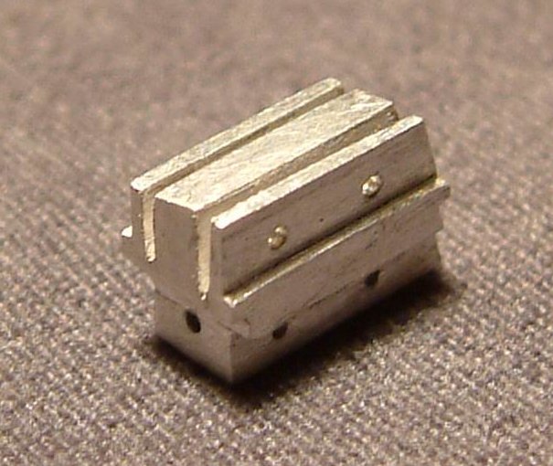
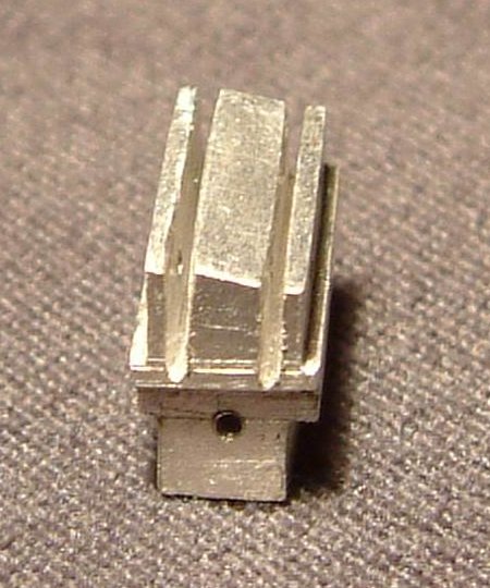
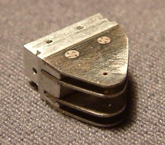
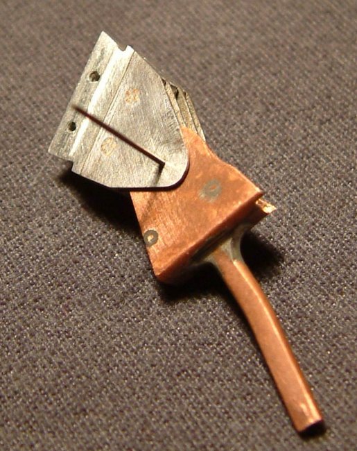
I decided to make the wing carry-through box ending of aluminium because
it is strong and light. To this element I fastened the plates of the material
similar to copper which can solder. All of these elements I’ve cut and file by
my own hands.
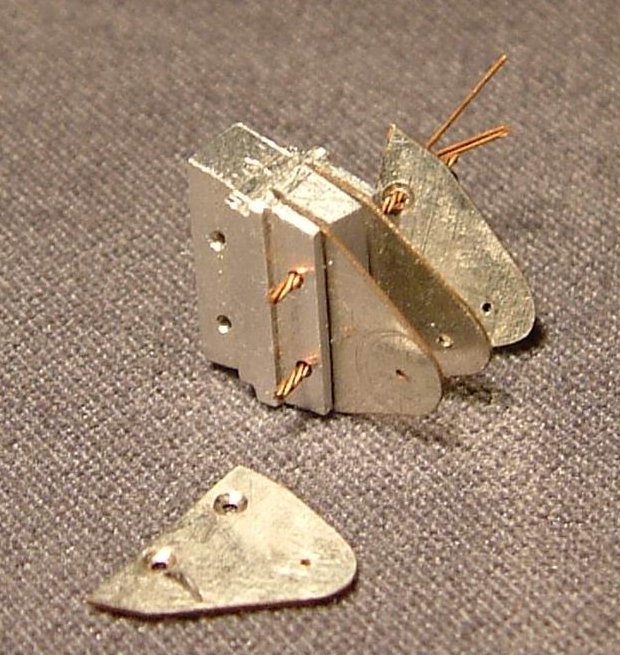
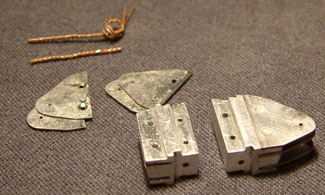
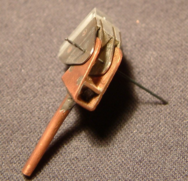
During works I invite very interesting way to fasten these metals without
the glue. As you can see the plates are putted in to the chinks in the
“aluminium cube”. I’ve drill apertures in aluminium part and in the plates.
Through these apertures I’ve planned put off, a single wire. But the
better idea was put a four thinner fixed wires. Try to look at the picture to
understand why. Four fixed wires I’ve set apart in the wide aperture end. Next
I’ve soldered it and filled. Very easy, isn’t it? Already element will be
fastened to wing carry-through box in the Tomcat fuselage, which I’m going to
make of plastic plates. The aluminium cube has special slits for plastic plates
and apertures (similar as in the plates case) for plugs.
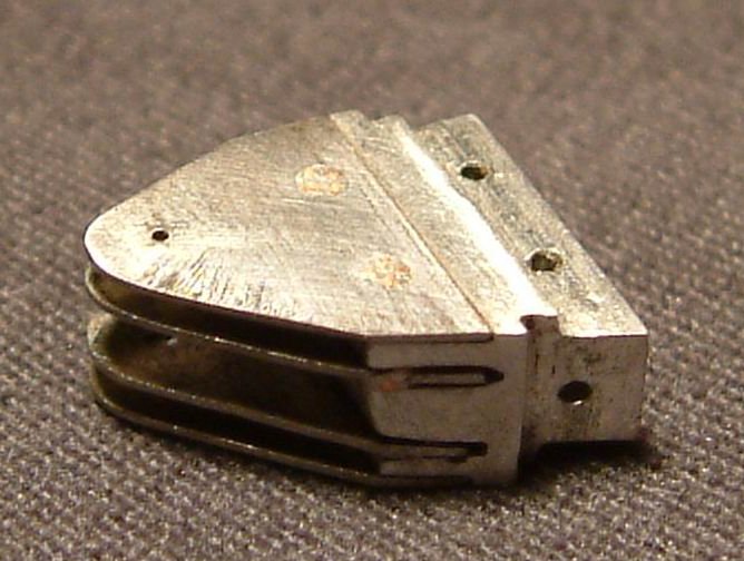
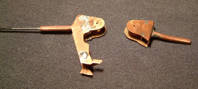
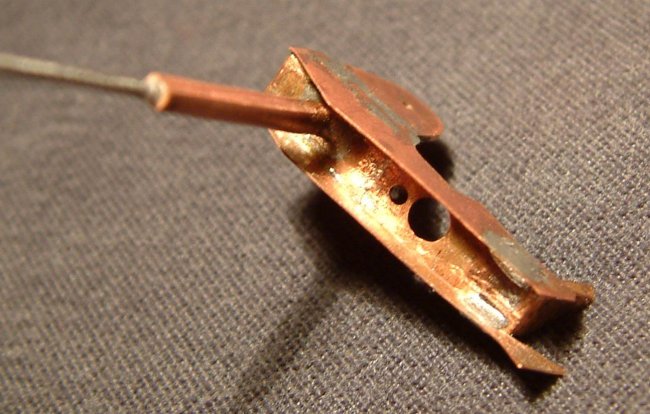
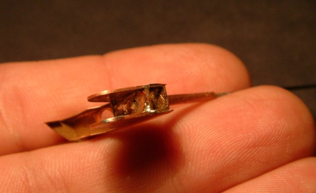
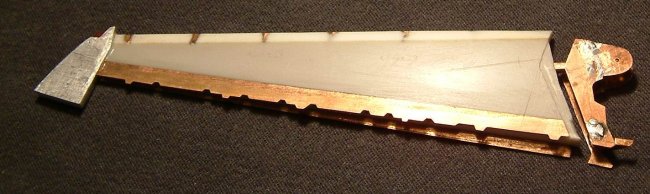
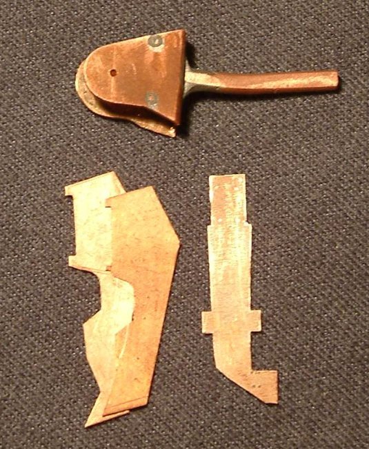
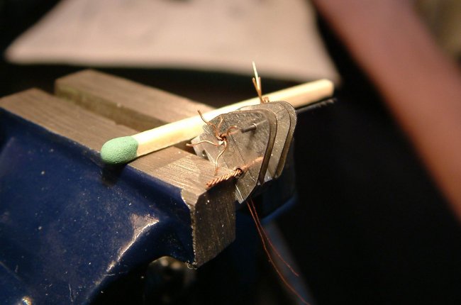
Finished element helped me in works on the wing jackscerw. In the model
it is double rounded almost parallel 0,5mm plates of copper. I decided to do it
from one piece of material to avoid separate them during soldering other parts
to them. After arching I filled exact shape of each plate. A whole part is a six
soldered together elements. Other smaller elements I’ll fasten after integrate
with the wing. As you can see there is a spar which I made longer by gluing a
needles. This is a very important to make the very strong wing.
A whole element will be finished already after integrate with wing. On
the pictures you can see some trashes and rests of the solders. That will be
removed after integrate. All of the parts, which you can see in this article
aren’t already finished. After the “hard works” I’ll polished it and
paint.
If
you have questions send me an e-Mail: mwitkowski@go2.pl
Marcin
in Poland
Pictures
and explanations
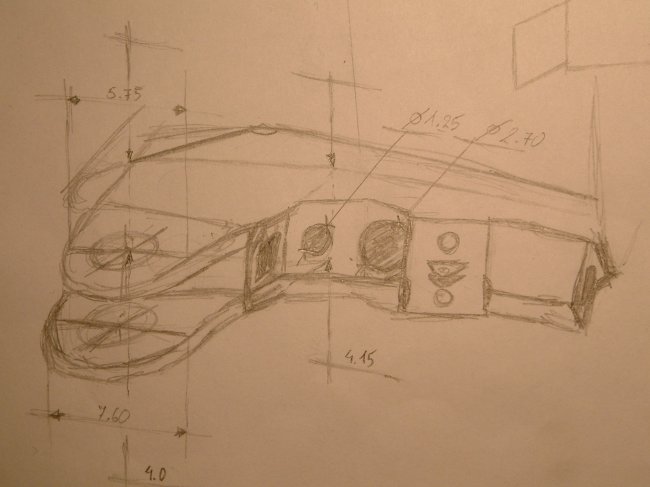
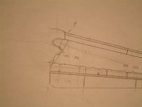
A
1/72 scale draw of the right F-14 wing witch jackscrew elements |
Click on
images below to see larger images
|
|
|
| Photos
of jackscrew and wing carry-through box ending. Source: www.anft.net/f-14
|
|
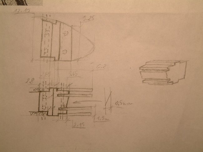
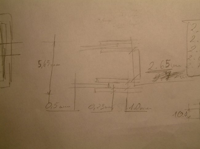
| Scale
draws of the “aluminium cube” on the special paper
|
|
| Left
side wing carry-through box ending parts
|
|
| Left
side wing carry-through box ending parts
|
|
| Left
side wing carry-through box ending parts |
|
|
Left
side wing carry-through box ending – “aluminium cube”
|
|
| Left
side wing carry-through box ending – “aluminium cube”
|
|
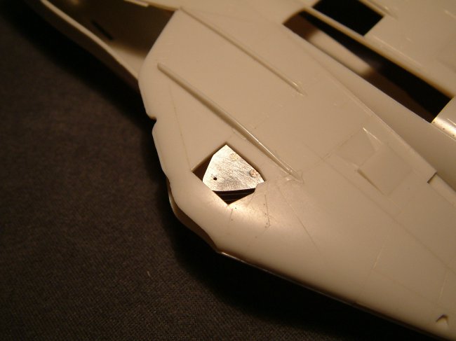
| Right
side wing carry-through box ending
|
|
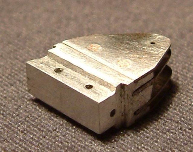
| Right
side wing carry-through box ending
|
|
| Right
side wing carry-through box ending
|
|
|
Both
wing carry-through box endings in different work steps |
|
| Both
jackscrews in different work steps |
|
| Left
wing jackscrew
|
|
| Left
wing jackscrew
|
|
| Left
wing jackscrew |
|
| A
whole mechanism after a meantime connect
|
|
|
A
whole mechanism after a meantime connect
|
|
| Left
wing with jackscrew an connect
|
|
|
Left
wing with jackscrew in almost connect position
|
|
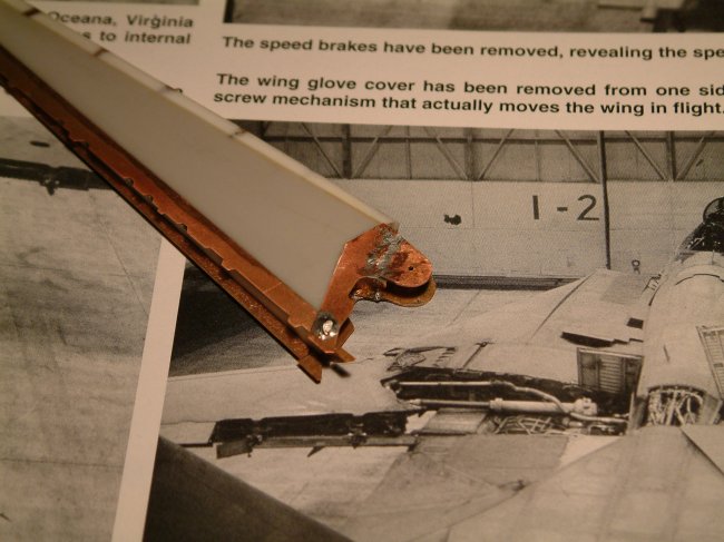
| Left
wing with connected jackscrew with picture of the real plane in background
|
|
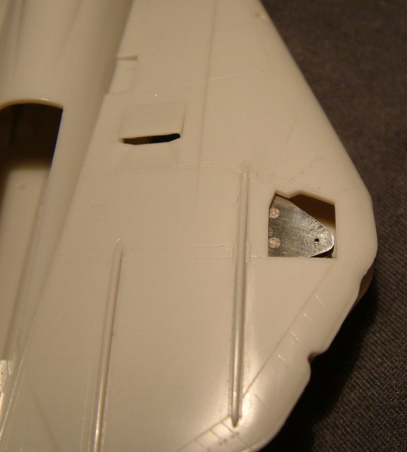
| Left
side wing carry-through box ending seeing through the access panel in the
fuselage |
|
| Left
side wing carry-through box ending seeing through the access panel in the
fuselage
|
|
|
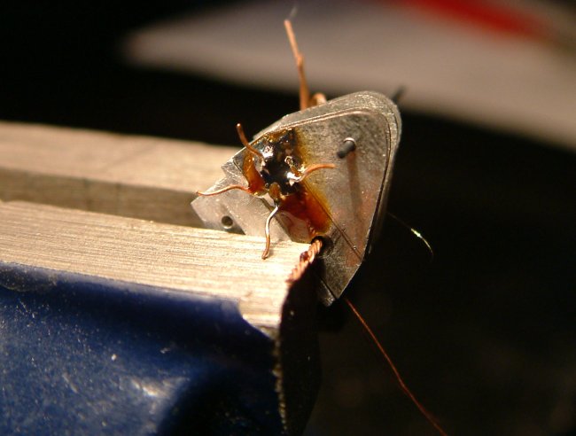
Not
already finished right side wing jackscrew
|
|
| Concept
draw of “aluminium cube”
|
|
| Concept
draw of jackscrew
|
|
| Concept
draw of jackscrew
|
|
| Left
jackscrew just before soldering
|
|
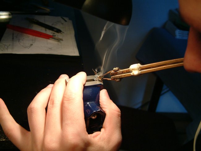
| Left
jackscrew during soldering
|
|
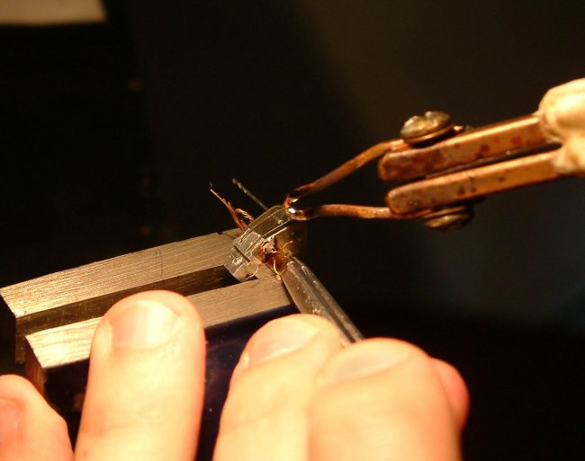
| Left
jackscrew during soldering
|
|
| Left
jackscrew after soldering
|
|
|