|
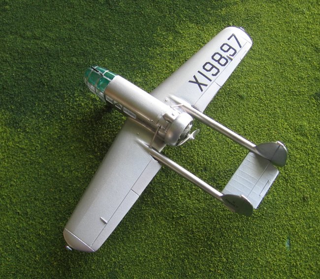
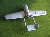
The Abrams Explorer was a functional and elegant plane specifically designed for
photographic survey. It first flew in 1937 being its performance, engineering
and configuration notable for the time. It went through a change of power plant
(from Wright R-975E to Wright R-975E-3, roughly 100 more hp) that implied the
subsequent addition of short struts and increased vertical surface area.
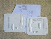
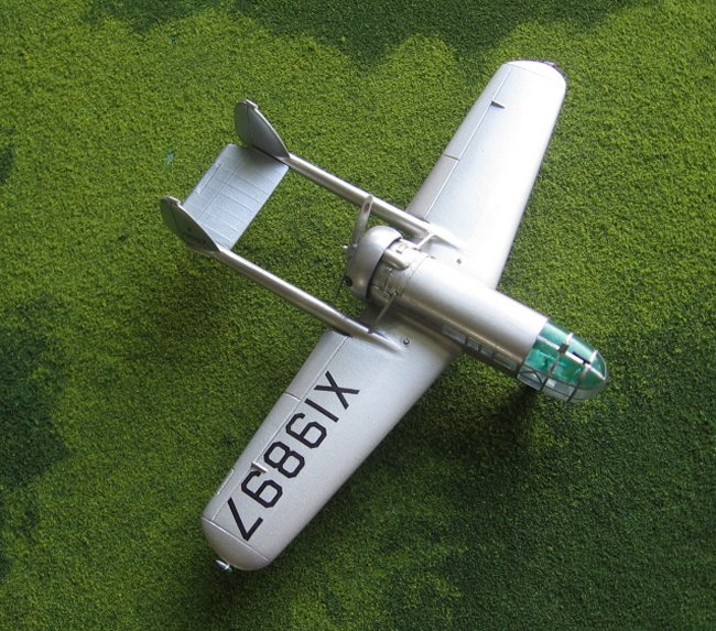
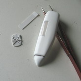
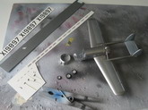
Execuform presents a vacuformed 1/72 kit in the simple lines that characterize
its offers. You get the main parts plus the transparencies and a plan with the
type technical description. It will take a bit of work, but again, it is highly
unlikely that you will get an Abrams Explorer from the mainstream manufacturers,
n’est pas?
This kit reminded me of early times of my life....I was flooded by memories of
the Modeling Monastery, with its walls of styrene reportedly scratchbuilt by the
original monks in the foggy beginnings of modeling history. In those cloisters
the monks were trained in the heavenly arts of vacuforming, the hard disciplines
of puttying and sanding and the mysteries of airbrushing.
Its
underground vaults stuffed with building materials and arcane tools, its
dungeons choked-full of the sanding dust produced by generations upon
generations of monks.
Those
were the times. But I digress....
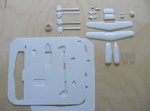
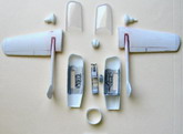
For the kit you have to provide engine, wheels, prop, decals and cater for the
interior bits. I decided to replace the stabilizer instead of spending time
sanding it down, but it is a matter of personal choice. Once the parts are
removed you are left with a backing sheet of large area, from where you can get
material for your scratched parts for this and future projects. The smaller
shapes are the front wheel fairing (two parts) the air scoops on the side of the
aft fuselage (two parts) a fairing on top of the aft fuselage (one part) and a
part to make the carb intake (goes at the bottom of the cowling that surrounds
the engine, see Execuform’s plan).
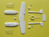
Click on
images below to see larger images
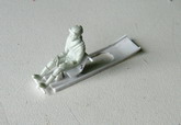
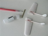
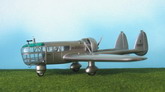
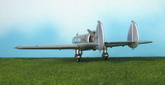
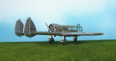
If you follow the images they will give you an idea of the construction process.
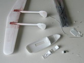
Wing halves and other twin parts like wheel pants and tail booms were glued at
this stage; once these parts were dry and sanded, the control surfaces’
separation lines were engraved. None of the model’s flying surfaces have the
ribbing that the real plane had. You may consider representing the ribbing with
your method of choice, subtly on the wings and a tad more prominent on the tail
surfaces. For the wing have in mind that the ribbing is seen on the aft two
thirds of the chord, on the exterior panels, excluding the flaps. I decided to
represent the fabric-covered parts with a different shade of paint.
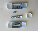
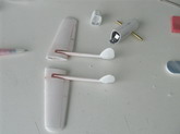
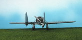
At this point it is of great help to start thinking about the building sequence.
A decision was made to glue the booms to the wing taking care of their alignment
(their bottoms don’t spoil the surface under the wing, only the top) and then
later cut the portion of the wing shadowed by the fuselage. The wings will at a
later stage be joined to the fuselage via a spar and the insertion of the
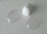
tailplane will close the structural circuit. The mating of the transparent part
of the fuselage with the opaque one also deserves some thought. The
transparencies are on the thin side, which is good for clarity, and not so good
for sanding and gluing. The parts will cover only the nose, so you have to cut
two side windows and insert a clear strip there –see images-. Later you could
glue the opaque fuselage sides –may be with an aft-closing bulkhead and some
interior- then saw the nose off. Some details that are located in the nose could
be added before gluing the frontal transparent parts. Those are separated
vertically in the mold, which is ok since a metal strip runs there on the
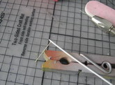
original plane. Decal strips would be used to depict the canopy frames. Caution
here because there are some curved ones at the doors. As per photos control lead
fairings and skids were added to the booms, while a “pan” was envisioned for
the cockpit details later to be inserted, as said, before closing everything up
with the transparent front part of the fuselage. A camera was also scratched and
its port holes drilled on the fuselage bottom. The instrument panel in the
original plane was small and attached to the roof. The roof of the canopy was
tinted, probably in a green hue, to provide for some sun screening.
Precautions are necessary to avoid a tail-sitter. I placed a bit of lead inside
the wings’ leading edges.
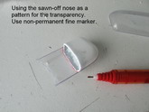
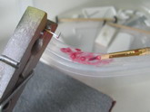
I found dealing with the provided front transparencies somewhat challenging and
a tad frustrating; I “adjusted” them too much, and had to buy a replacement
set from Execuform. As said, those transparencies are thin, so you don’t have
much edge where to glue, and matching the halves with the thickness of stiff
paper is not a pleasant task. And at the same time you have to match the cross
section at the front of the sawn-off fuselage. Once the transparencies were
adjusted to size I tried different glues on scrap pieces. Tenax, Model Master
liquid cement and Plastruct Plastic Weld didn’t work well, so I Futurized them
and glued them with cyanoacrylate. My suspicions that the frontal area of the
model would consume most of the building time proved right.
Retrospectively
thinking, I think that to build the wing, booms and tail as a unit and then cut
a niche in the fuselage to accommodate it is a better prospect. Even more
retrospectively thinking I shouldn’t be building models at all. Furthermore, I
shall be in an intergalactic ship in a discovery voyage through the universe,
where no modeler has gone before.
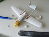
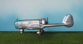
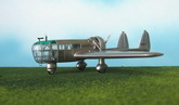
In any case the subassemblies (plane, front wheel housing and annular cowl) were
primed and then a coat of black enamel was sprayed on in preparation for the
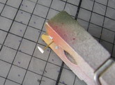
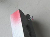
aluminum finish.
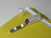
Venturi and
Pitot probes were made and set aside, together with the home-made decals and
navigation lights (for the later a step-by-step process is depicted in the
accompanying images). I ended up adapting a stunning resin engine from Khee-Kha
Art Products to be able to finish the model.
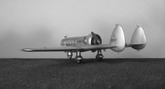
There are enough images on the Net to have a very good idea of the real plane
and detail it if so you wish. Just beware that the window
panes are not symmetrically laid on both sides.
Now it is
time for a nice little simple kit to have some rest. Hum, where was that
Heller’s Caudron Simoun?
Thanks to Jim Schubertus the Epicurean and his Furry Black Midget Seals’
Circus, and also to the other fellow modelers that provided input on the
project.
Gabriel Stern
Click on
images below to see larger images
|